
 EN
EN
Can Cable Gland Prevent Cable Pulling Damage?
The short answer is yes — but only when the cable gland is correctly sized for the cable and properly installed. Many buyers assume that fitting any cable gland automatically protects wiring at enclosure entry points. In practice, the mechanical protection a cable gland provides depends entirely on whether the sealing insert grips the cable sheath and whether the locknut is tightened to the correct torque. Get either of those wrong, and the cable gland becomes a passive fitting rather than a genuine mechanical safeguard.
What a Cable Gland Is Actually Designed to Do
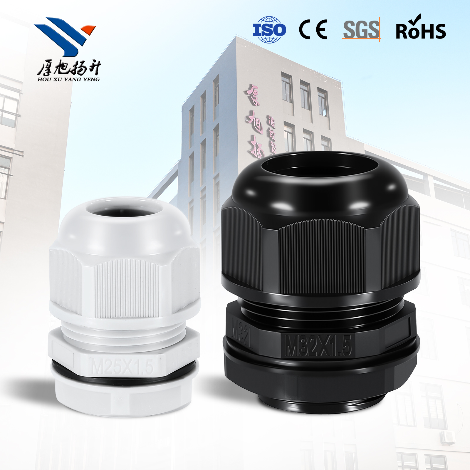
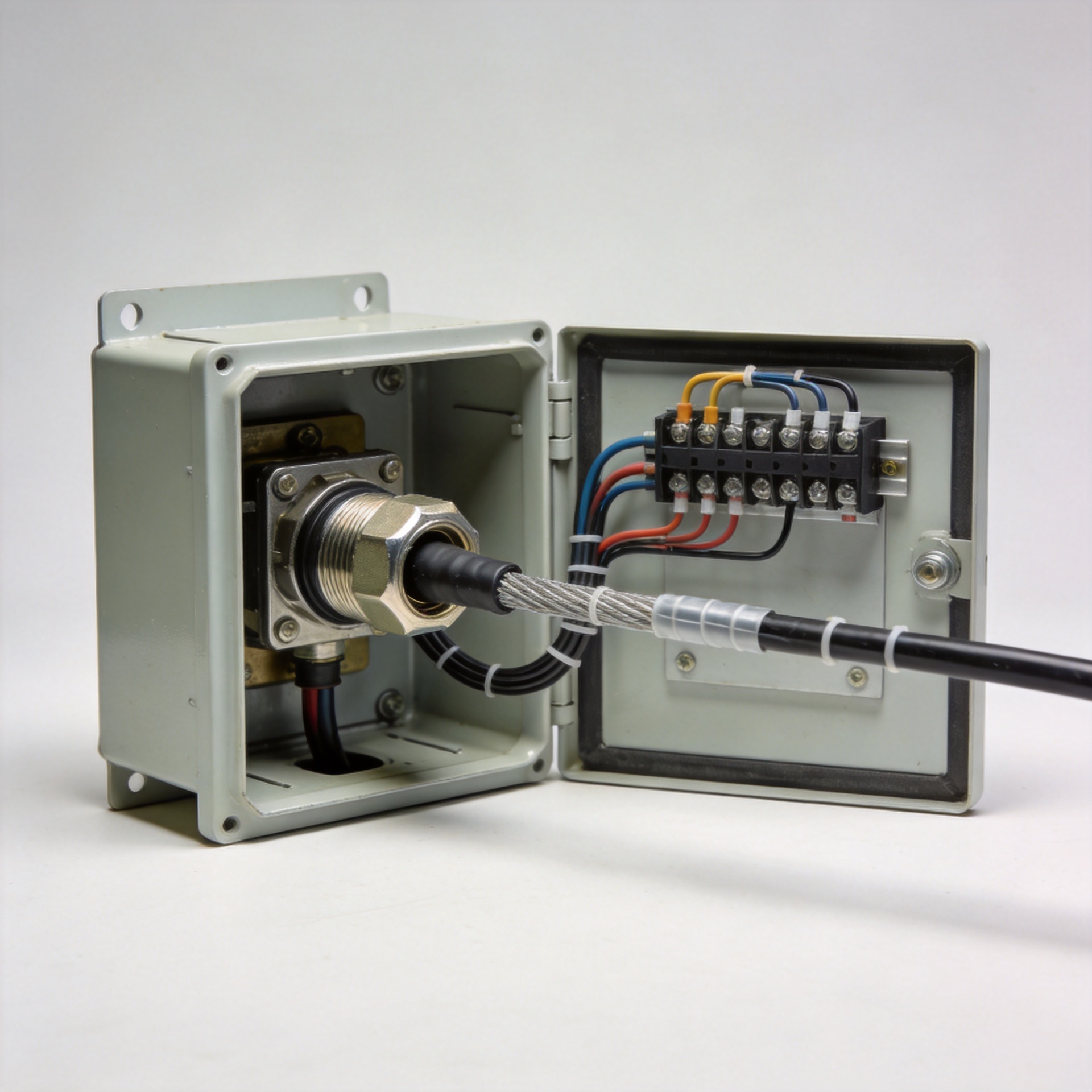
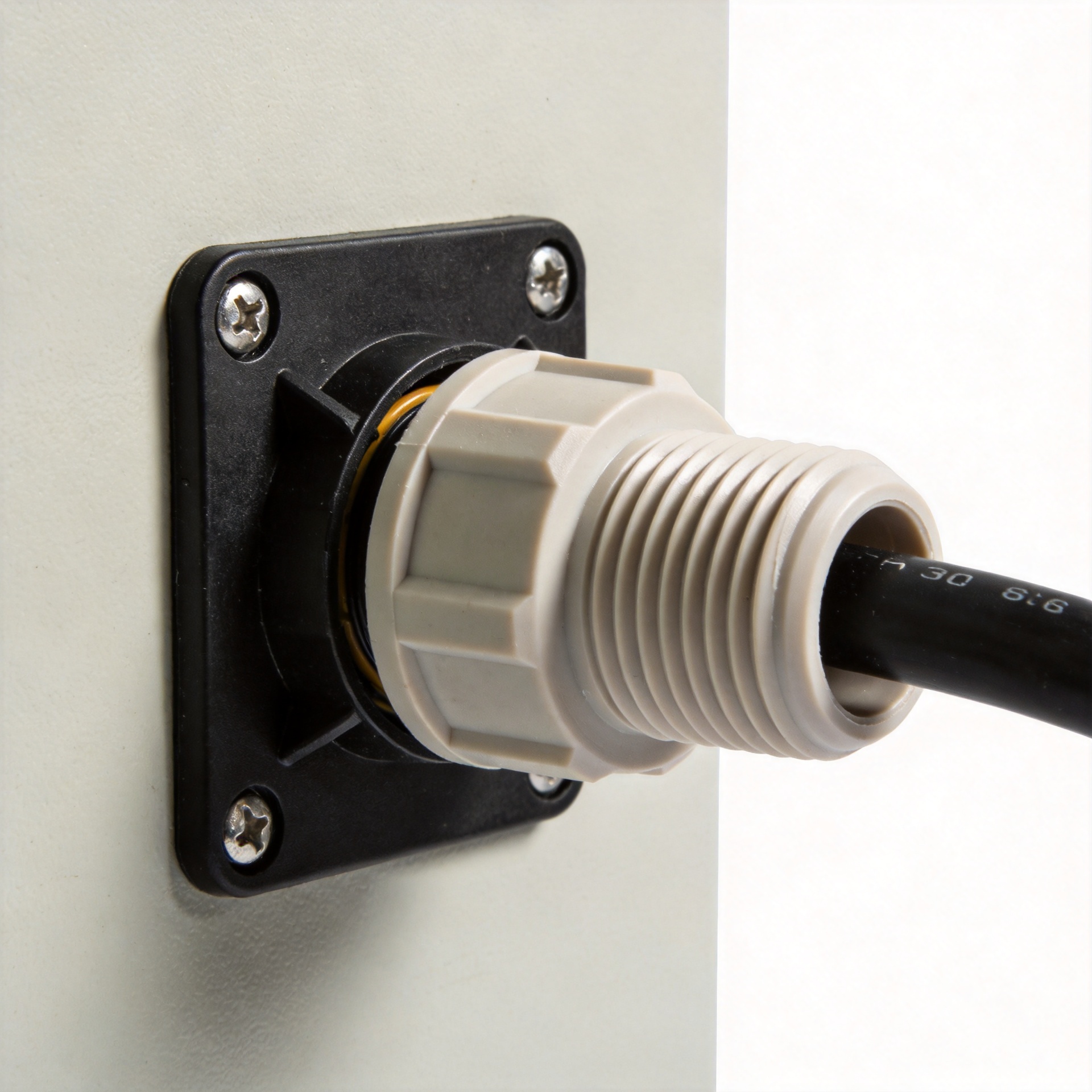
A cable gland performs two distinct functions, and buyers sometimes treat them as the same thing. The first is sealing: excluding dust, water, and contaminants from the enclosure (this is what IP ratings measure). The second is strain relief: resisting mechanical forces at the cable entry point so that tensile pulling, torsion, and bending forces are absorbed by the cable gland body rather than transmitted to the terminations and connections inside the panel.
Both functions are addressed under DIN EN 62444, the international standard covering cable glands for electrical installations. The mechanical resistance requirements within that standard specify that a correctly installed cable gland must resist a defined pull-out force without the cable slipping through. When that criterion is met, the cable gland is doing exactly what the question asks about — preventing pulling damage at the enclosure entry.
It sounds counterintuitive, but the strain relief function depends more on the sealing insert than on the cable gland body itself. The clamping ring or sealing insert is the component that grips the cable sheath. If the insert does not compress properly against the cable's actual outer diameter, you get neither a reliable IP seal nor effective pull-out resistance — regardless of how tightly the locknut is fitted.
When a Cable Gland Fails to Prevent Pulling Damage
Before finalizing a cable gland specification, ask yourself: do you know the actual outer diameter of the cable being fitted — including the variation that can exist between different drum batches of the same cable type?
The most common reason a cable gland fails to prevent pulling damage is a clamping range mismatch. Every cable gland has a defined clamping range: the minimum and maximum cable outer diameter it can grip effectively. If the cable's actual OD falls near the lower end of that range — or outside it entirely; the sealing insert cannot compress far enough to create adequate grip. The cable entry looks correct from the outside but provides minimal pull-out resistance in service.
The second failure mode is installer over-tightening. The instinct when fitting a plastic cable gland is to tighten the locknut firmly to make sure it holds. In practice, excessive torque deforms or cracks the clamping ring — the same component responsible for gripping the cable sheath. The result is a cable gland that looks correctly fitted but has a damaged insert that provides no real mechanical resistance to pulling. This damage is usually not visible externally, which is why it often escapes installation inspection.
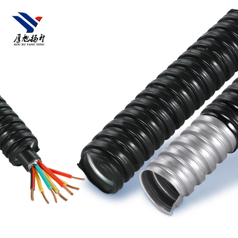
The third scenario is where standard cable gland protection genuinely does not apply: armored cable. A standard cable gland grips the outer cable sheath. For steel wire armored (SWA) or aluminum wire armored (AWA) cable, the mechanical load in service is carried by the armoring layer, not the outer sheath. A cable gland that grips only the outer jacket does not address armor pull-back — which allows the cable core to gradually shift position inside the panel as the installation flexes over time. Armored cable entries require a cable gland with a dedicated clamping element that engages the armor layer directly.
How to Select a Cable Gland That Reliably Prevents Pulling Damage
In practical terms, the cable gland installations that hold up over years of service — through maintenance access cycles, vibration, and conduit movement — tend to be the ones where actual cable OD was measured rather than estimated from nominal cross-section data.
For pulling damage prevention, evaluate three factors in sequence:
- Clamping range alignment: Measure the cable's actual outer diameter and confirm it sits in the middle portion of the cable gland's stated clamping range. Cables at the extreme ends of a clamping range are gripped less reliably. Cable glands with a wider clamping range per nominal size reduce risk in projects where the same cable gland size must accommodate OD variation across different cable constructions or manufacturers.
- Locknut torque retention for the environment: In motor control panels, pump stations, and machine enclosures — applications with continuous or intermittent vibration — standard locknuts can gradually back off under cyclic loading and progressively lose the clamping force that provides pull-out resistance. A cable gland designed with vibration-resistant torque retention maintains grip integrity over the installation's service life. This matters more than material grade in high-vibration environments.
- Gland type matched to cable construction: Standard cable glands for non-armored flexible or multi-conductor sheathed cable. Armored cable glands with armor clamping elements for SWA and AWA cable. These are not interchangeable at the mechanical protection level, even if the thread and nominal size match.
The Corrected Understanding
A cable gland prevents cable pulling damage through strain relief — not by acting as a physical barrier. The protection mechanism is gripping: the sealing insert compresses against the cable sheath and transfers any external tensile force to the cable gland body and the enclosure panel, keeping that force away from the terminations and connections inside.
That gripping function only works when the cable gland is sized so the cable OD falls within an effective zone of the clamping range, and the locknut is tightened to the manufacturer's specified torque. An insert that cannot close around the cable's actual diameter cannot grip it. A damaged insert from over-tightening cannot grip it either. A cable gland fitted to the outer sheath of an armored cable grips the wrong layer and misses the actual load path.
For panel builders, contractors, and project engineers specifying cable entries on equipment subject to service loads, vibration, or regular maintenance access, the selection process for a cable gland that will genuinely prevent pulling damage is straightforward: measure actual cable OD, match it to a cable gland with an appropriate clamping range, match the cable gland type to the cable construction, and install to torque specification. When all four steps are followed, the cable gland fulfills its strain relief function and protects the cable at the entry point throughout the installation's service life.
Suppliers who carry a complete cable gland range across IP ratings, clamping ranges, and cable types allow project engineers to specify the correct variant for each entry without switching between product families or sourcing from multiple vendors — which simplifies both specification and site material management on multi-entry panel installations.